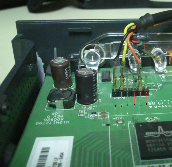

- DEBRICK ROUTER SERIAL INSTALL
- DEBRICK ROUTER SERIAL SERIAL
- DEBRICK ROUTER SERIAL DRIVERS
- DEBRICK ROUTER SERIAL DRIVER
- DEBRICK ROUTER SERIAL PC
NOTE: the OS (Linux->DD-WRT) reset command Hard_reset_or_30/30/30#Erasing_NVRAM depends on the build/date. Bad nvram values are often the cause of bricked routers. The most common CFE command is "nvram erase". `devinfo set " can be used to change values. To see the built-in CFE default parameters (restored after a `nvram erase` or reset): NOTE: Ensure the Scroll Lock key is off and Flow Control is off or none, or the boot will not stop. It helps to get someone to help with this process, or have good dexterity. The time window to do this is less than a second or two. Do this by rapidly hitting Cntl-C (tpl for TP-Link routers) JUST as the router is starting up.

' There is less than a second at power-up to break CFE and stop the boot, thus allowing keyboard entry in a terminal. I have purchased a few of the Nokia clones that didn't work, for that reason I buy USB to uart adapters like these. Windows XP mode is the solution in such a case.
DEBRICK ROUTER SERIAL DRIVER
Cheap CA-42 is ok, even the Chinese clone with ARK3116 chip, thus you will not find proper driver for Win7 64bit system.
DEBRICK ROUTER SERIAL SERIAL
The "level shifting 3.3v TTL adapter" is a must, you can't connect router straight to standard RS232 serial interface. My first CA-42 had 3 wires and the ones I bought later had 5, the picture in my post above is from one of those.You can carefully remove the plastic molding of the phone connector and see where each wire is going and find out which colour the respective signals are on. No there is no fixed standard for the colours of the wires and obviously not on the number of wires either.
DEBRICK ROUTER SERIAL DRIVERS

DEBRICK ROUTER SERIAL PC
You connect and talk to the router from a PC using terminal/console programs such as: On routers with two Serial ports (Tx0/Tx1 and Rx0/Rx1), use the "0" ports for your connections (I've not seen a router yet that connects to the "1" side). Rx and Tx are labeled relative to the cable, so Rx line needs connected to the router's Tx, because the router labels are also relative to it, so Tx and Rx get crossed for proper connection. Then you can guess at the Rx and Tx lines. Some boards are NOT marked with pin designation, so use a multimeter to determine power and ground to avoid shorting the serial cable TTL chip. There are three or four connections for serial to function properly: Vcc (+3.3V, but usually not connected), GND, Tx and Rx. Serial cable can be either USB or DB9 connection type and be capable of voltage level shift to +3.3V, not +5V. Some routers have serial ports inside the WAN port, and here is a link to some Serial port pinouts.
DEBRICK ROUTER SERIAL INSTALL
Unless it has an OEM header, you have to either solder the wires to the pads, or remove solder from the holes to install an appropriate header. Serial ports are normally four or five pins on the router board. The last resort is to desolder the flash chip and use a programmer to flash CFE (if needed) and firmware. Otherwise JTAG is required to debrick, if available, which can also replace a corrupted CFE. Routers with a serial port AND working CFE (bootloader) can often be recovered with a serial adapter, using CFE low-level commands.


 0 kommentar(er)
